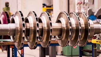
Description
Function of a Compressor Rotor Assembly
The primary function of the rotor assembly is to rotate the compressor’s aerodynamic components and transfer mechanical energy to the air.
A rotor assembly may:
- Carry one or more compressor impellers
- Transfer rotational energy from the drive system
- Rotate at the required compressor operating speed
- Maintain the correct relationship between compressor stages
- Work with bearings and seals to maintain stable rotation
- Transfer torque through the compressor shaft
- Support the aerodynamic components throughout operation
In geared centrifugal compressors, the rotor may be driven through a pinion or other gear arrangement.
Main Components of a Rotor Assembly
Depending on compressor design, a balanced rotor assembly may contain:
- Compressor shaft
- Impellers
- Shaft sleeves
- Spacers
- Thrust components
- Balance components
- Keys or locking arrangements where applicable
- Retaining components
- Rotor-mounted seals or sleeves
- Other manufacturer-specific components
The exact assembly configuration varies between compressor manufacturers and models.
Importance of Rotor Balancing
Centrifugal compressor rotors operate at high rotational speeds. Even a relatively small mass imbalance can generate significant centrifugal forces as rotational speed increases.
Precision balancing helps to reduce:
- Excessive vibration
- Bearing loading
- Shaft deflection
- Mechanical stress
- Coupling vibration
- Premature bearing wear
- Seal problems
- Rotor dynamic instability
The required balancing procedure and acceptance criteria should follow the applicable compressor manufacturer’s specifications and engineering requirements.
What Does “Balanced Rotor Assembly” Mean?
A balanced rotor assembly is one in which the distribution of rotating mass has been evaluated and corrected to meet the required balance condition for its intended operating speed and application.
Balancing may involve controlled correction of the rotating assembly so that its mass distribution is within the specified tolerance.
Depending on the compressor and rotor design, balancing may be performed as:
- Component balancing
- Sub-assembly balancing
- Complete rotor balancing
- High-speed balancing where required
The appropriate balancing method depends on the compressor’s rotor-dynamic characteristics and manufacturer’s requirements.
Rotor Dynamic Considerations
A centrifugal compressor rotor is not simply a static rotating component. Its behavior at operating speed depends on factors such as:
- Rotor mass distribution
- Shaft stiffness
- Bearing characteristics
- Operating speed
- Critical speeds
- Damping
- Impeller arrangement
- Seal clearances
- Coupling arrangement
- Operating temperature
For this reason, a replacement rotor assembly must be compatible with the original compressor’s rotor-dynamic design.
Rotor Assembly Construction
Rotor shafts are generally manufactured from high-strength engineering materials selected for the compressor’s speed, mechanical loads, and operating environment.
Depending on the original design, materials may include:
- Alloy steels
- Forged steels
- Heat-treated shaft materials
- Application-specific engineering alloys
Impellers and other rotor-mounted components may use materials appropriate to the compressor’s air conditions, temperature, speed, and mechanical requirements.
Material and heat-treatment specifications should be matched to the original engineering design.
Impeller and Shaft Compatibility
The impellers mounted on a rotor must be correctly matched to the shaft and stage arrangement.
Important considerations include:
- Impeller bore dimensions
- Shaft diameter
- Impeller mounting method
- Key or locking arrangement
- Axial positioning
- Stage sequence
- Impeller orientation
- Rotor length
- Spacer dimensions
- Balance condition
Incorrect assembly can affect rotor balance, stage performance, clearances, and overall compressor reliability.
Rotor Assembly and Bearings
The rotor operates within a bearing system that supports the shaft and controls its radial and axial movement.
Depending on the compressor design, the rotor may operate with:
- Radial bearings
- Journal bearings
- Tilting-pad bearings
- Thrust bearings
- Other specialized bearing arrangements
The rotor shaft journals must be manufactured and finished to the dimensional requirements of the corresponding bearings.
Rotor Seals and Clearances
Rotor assemblies operate with carefully controlled clearances between rotating and stationary components.
These may include:
- Shaft seal clearances
- Labyrinth seal clearances
- Impeller clearances
- Diffuser clearances
- Bearing-related clearances
- Other internal running clearances
Excessive or insufficient clearance can affect compressor efficiency, leakage, temperature, vibration, or component reliability.
Common Rotor Assembly Problems
Rotor assemblies can experience mechanical or aerodynamic problems during prolonged operation.
Common issues include:
- Rotor imbalance
- Shaft bending
- Shaft runout
- Impeller damage
- Impeller erosion
- Corrosion
- Rubbing
- Seal damage
- Key or locking-component wear
- Bearing journal wear
- Fatigue-related damage
- Excessive vibration
- Rotor dynamic instability
The underlying cause should be investigated before replacing or rebuilding a rotor assembly.
Causes of Rotor Imbalance
Rotor imbalance can develop because of:
Impeller Damage
Erosion, foreign-object damage, corrosion, cracking, or material loss can change the rotor’s mass distribution.
Deposits
Material deposits on rotating surfaces can create uneven mass distribution.
Incorrect Assembly
Incorrect positioning of rotor components or incorrect assembly procedures can affect balance.
Component Replacement
Replacing an individual rotor-mounted component without maintaining the required balance condition can affect the complete assembly.
Shaft Damage
Bending or dimensional changes in the shaft can affect rotor running characteristics.
Rotor Inspection
During a compressor overhaul, the rotor assembly may be inspected for dimensional and mechanical condition.
Inspection can include:
- Visual inspection
- Shaft runout measurement
- Journal diameter inspection
- Impeller inspection
- Checking for rubbing
- Checking for erosion and corrosion
- Checking rotor-mounted components
- Inspecting keys and locking arrangements
- Checking axial dimensions
- Inspecting seal surfaces
- Checking balance condition
- Non-destructive testing where required
The inspection scope should follow the compressor manufacturer’s maintenance requirements and the condition of the rotor.
Rotor Balancing
Rotor balancing should be performed using appropriate balancing equipment and procedures.
Depending on the compressor design, the process may involve:
- Inspection of the complete rotor assembly
- Verification of component dimensions
- Assembly according to the specified configuration
- Measurement of the rotor’s balance condition
- Controlled correction where required
- Verification of the final balance condition
- Documentation of the balancing result
For high-speed compressor rotors, balancing requirements can be highly specific to the rotor design and operating speed.
High-Speed Balancing
Certain compressor applications may require balancing at speeds representative of the rotor’s operating conditions or according to a specified balancing procedure.
High-speed balancing can provide additional information about rotor behavior, including dynamic response under rotation.
Whether high-speed balancing is required depends on the compressor design, rotor type, operating speed, and applicable engineering specifications.
Replacement of Rotor Assemblies
A replacement rotor assembly must be matched precisely to the original compressor.
Important parameters include:
- Compressor manufacturer
- Compressor model
- Compressor serial number
- Rotor assembly part number
- Rotor shaft dimensions
- Overall rotor length
- Operating speed
- Number of stages
- Impeller configuration
- Impeller dimensions
- Bearing journal dimensions
- Thrust arrangement
- Seal arrangement
- Rotor weight
- Material
- Heat treatment
- Balance requirements
- Rotation direction
- Coupling or gear arrangement
A rotor should not be selected based solely on shaft diameter or overall dimensions.
Rotor Assembly Selection Specifications
| Parameter | Requirement |
|---|---|
| Component | Balanced Rotor Assembly |
| Equipment | Centrifugal Air Compressor |
| Compressor Make | As per equipment |
| Compressor Model | As per equipment |
| Compressor Serial Number | As available |
| Rotor Part Number | As per original component |
| Rotor Type | As per compressor design |
| Number of Stages | As specified |
| Operating Speed | As specified |
| Rotor Length | As per original design |
| Shaft Diameter | As specified |
| Journal Dimensions | As specified |
| Impeller Arrangement | As per compressor |
| Impeller Material | As specified |
| Shaft Material | As specified |
| Heat Treatment | As required |
| Balance Requirement | As per engineering specification |
| Rotation Direction | As specified |
| Seal Arrangement | As per compressor |
| Thrust Arrangement | As applicable |
| Coupling / Gear Arrangement | As specified |
| Application | High-speed centrifugal compressor rotor |
Rotor Assembly Maintenance and Handling
Rotor assemblies require careful handling during transportation, storage, installation, and maintenance.
Recommended practices include:
- Protecting precision-machined surfaces
- Preventing impact or dropping
- Protecting bearing journals
- Keeping sealing surfaces clean
- Preventing corrosion during storage
- Maintaining correct lifting arrangements
- Using appropriate rotor supports
- Avoiding unnecessary movement of balanced assemblies
- Verifying alignment during installation
- Following the manufacturer’s assembly procedure
A balanced rotor should be protected from damage or unauthorized modification after balancing.
Why Choose Aegis Projects?
Aegis Projects Technology provides industrial compressor spare parts and replacement rotating components for centrifugal air compressor systems.
Our balanced rotor assembly solutions can be evaluated according to the compressor’s original rotor configuration, operating speed, stage arrangement, shaft dimensions, impeller configuration, bearing arrangement, and balancing requirements.
We support requirements for:
- Balanced centrifugal compressor rotor assemblies
- Compressor shafts
- Rotor assemblies with impellers
- Replacement rotating assemblies
- Compressor overhaul components
- Impeller and rotor components
- Rotor balancing requirements
- Replacement and retrofit solutions
For accurate identification, share the compressor make, model, serial number, rotor part number, photographs, rotor drawings, shaft dimensions, impeller details, operating speed, or existing rotor documentation wherever available.
Request a Quote
Looking for a balanced rotor assembly for a centrifugal air compressor?
Contact Aegis Projects Technology Pvt. Ltd. with your compressor and rotor details. Our team can assist with identifying a suitable replacement or equivalent rotor assembly for your compressor application.