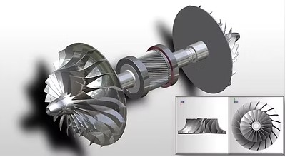
Description
Function of Pinions
The primary function of a pinion is to transmit mechanical power through the compressor gear train.
Depending on the compressor design, a pinion may:
- Transfer power between the bullgear and compressor rotor
- Increase rotor speed relative to the driving shaft
- Provide the required gear ratio
- Transfer torque to compressor stages
- Maintain synchronized rotation of geared compressor elements
- Support efficient power transmission
- Operate as part of a high-speed gear assembly
The exact pinion arrangement varies according to the centrifugal compressor’s gearbox and rotor configuration.
How a Pinion Works
In a geared centrifugal compressor, the driving element rotates the main gear or bullgear. The bullgear meshes with one or more smaller pinions.
Because the pinion generally has fewer teeth than the mating bullgear, the gear arrangement can increase the rotational speed of the pinion shaft.
The pinion shaft can then drive the corresponding compressor rotor at the speed required by the aerodynamic design of the compressor stage.
The gear relationship must maintain accurate tooth engagement while transmitting the required torque at high rotational speed.
Pinion and Bullgear Arrangement
A typical geared centrifugal compressor may contain:
- Bullgear
- One or more pinions
- Pinion shafts
- Compressor rotors
- Bearings
- Thrust bearings
- Lubrication system
- Gear housing
The bullgear and pinions form a precision gear train. Their tooth geometry, center distance, backlash, alignment, lubrication, and surface condition must remain within the applicable design requirements.
Pinion Construction
Pinions for industrial centrifugal compressors are generally manufactured from high-strength engineering materials suitable for high-speed and high-load gear applications.
Depending on the design, construction may involve:
- Forged alloy steel
- Hardened alloy steel
- Case-hardened gear materials
- Precision-machined gear teeth
- Integral or separately assembled shafts
- Ground or precision-finished tooth surfaces
The material and heat-treatment specification should be matched to the original compressor design.
Gear Tooth Design
Pinion performance depends heavily on accurate tooth geometry.
Important characteristics can include:
- Number of teeth
- Module or diametral pitch
- Pressure angle
- Helix angle where applicable
- Face width
- Pitch diameter
- Root diameter
- Outside diameter
- Tooth profile
- Backlash
- Tooth modification
- Surface finish
The exact values must be matched to the mating gear and compressor design.
Pinion Shafts
Depending on the compressor configuration, the pinion may incorporate or be mounted on a precision-machined shaft.
The shaft transfers torque between the gear teeth and the compressor rotor.
Important shaft characteristics may include:
- Shaft diameter
- Bearing journal dimensions
- Rotor mounting arrangement
- Keyway or spline arrangement where applicable
- Coupling arrangement
- Runout
- Concentricity
- Surface finish
Accurate shaft geometry is essential for maintaining proper alignment and minimizing vibration during high-speed operation.
Gear Materials and Heat Treatment
Pinions operate under significant cyclic loads and require suitable resistance to wear, fatigue, and surface damage.
Depending on the original specification, pinions may use alloy steels with appropriate heat treatment such as:
- Case hardening
- Carburizing
- Nitriding
- Through hardening
- Other manufacturer-specified treatments
The required hardness profile and heat-treatment process should be based on the original gear design and engineering specification.
Importance of Pinion Alignment
Correct alignment between the pinion and mating bullgear is essential for reliable operation.
Incorrect alignment can result in:
- Uneven tooth loading
- Localized tooth wear
- Increased vibration
- Gear noise
- Increased heat generation
- Premature bearing loading
- Tooth surface damage
- Reduced gear life
Gear alignment should therefore be checked during compressor assembly, overhaul, and major maintenance activities.
Pinion Lubrication
Proper lubrication is essential for high-speed gear operation.
Lubricating oil helps to:
- Reduce friction
- Reduce tooth-surface wear
- Remove heat generated at the gear mesh
- Protect gear surfaces from corrosion
- Support smooth gear engagement
- Extend gear-component service life
Oil flow, pressure, temperature, cleanliness, and viscosity should remain within the compressor manufacturer’s specified operating range.
Common Pinion Problems
Pinions can develop wear or damage due to lubrication problems, misalignment, excessive loading, contamination, or long-term operation.
Common issues include:
- Tooth wear
- Pitting
- Micropitting
- Scuffing
- Scoring
- Tooth surface fatigue
- Tooth chipping
- Tooth cracking
- Gear backlash changes
- Shaft wear
- Bearing journal damage
- Excessive runout
- Corrosion
- Abnormal vibration
The cause of gear damage should be identified before installing a replacement pinion to reduce the risk of repeat failure.
Pinion Failure Causes
Inadequate Lubrication
Insufficient oil flow, incorrect oil viscosity, contamination, or high oil temperature can affect gear-surface protection.
Gear Misalignment
Incorrect center distance, shaft alignment, bearing condition, or assembly alignment can cause uneven tooth loading.
Excessive Loading
Operating conditions outside the design requirements can increase tooth stresses and accelerate fatigue.
Contaminated Lubricant
Particles or other contaminants in the lubrication system can damage precision gear surfaces and bearings.
Improper Backlash
Incorrect backlash can cause abnormal tooth contact, heat generation, noise, and accelerated wear.
Bearing Problems
Worn or damaged bearings can alter shaft position and consequently affect gear-mesh alignment.
Inspection of Pinions
During compressor overhauls, pinions should be inspected for signs of wear and surface damage.
Inspection may include:
- Visual inspection of tooth surfaces
- Checking for pitting
- Checking for scoring and scuffing
- Inspecting tooth edges
- Checking for cracks
- Measuring backlash
- Checking tooth-contact pattern
- Checking shaft runout
- Inspecting bearing journals
- Checking dimensions
- Checking gear alignment
- Inspecting lubrication passages where applicable
- Performing non-destructive testing when required
Inspection methods should be selected according to the compressor manufacturer’s maintenance procedures and applicable engineering standards.
Replacement of Pinions
A replacement pinion must be precisely matched to the existing gear train.
Important selection parameters include:
- Compressor manufacturer
- Compressor model
- Compressor serial number
- Existing pinion part number
- Number of teeth
- Gear module or pitch
- Pressure angle
- Helix angle where applicable
- Pitch diameter
- Face width
- Gear ratio
- Shaft dimensions
- Bearing journal dimensions
- Material
- Heat treatment
- Tooth hardness
- Rotation direction
- Mounting arrangement
- Mating bullgear specifications
A pinion should not be selected solely by physical dimensions because even small differences in tooth geometry can affect gear-mesh performance.
Pinion Balancing and Precision
High-speed compressor gear assemblies require accurate manufacturing and dimensional control.
Depending on the design, the pinion assembly may require verification of:
- Concentricity
- Shaft runout
- Gear eccentricity
- Dynamic balance
- Tooth geometry
- Surface finish
- Bearing journal dimensions
These characteristics help maintain stable operation at the compressor’s designed rotational speed.
Applications
Pinions are used in geared centrifugal compressor systems across industries including:
- Manufacturing plants
- Steel plants
- Cement plants
- Power plants
- Chemical industries
- Petrochemical facilities
- Refineries
- Pharmaceutical manufacturing
- Food and beverage industries
- Automotive manufacturing
- Textile industries
- Process industries
- Industrial compressed-air plants
Pinion Selection Specifications
| Parameter | Requirement |
|---|---|
| Component | Pinion |
| Equipment | Geared Centrifugal Air Compressor |
| Compressor Make | As per equipment |
| Compressor Model | As per equipment |
| Compressor Serial Number | As available |
| Pinion Part Number | As per original component |
| Number of Teeth | As per gear design |
| Gear Module / Pitch | As specified |
| Pressure Angle | As specified |
| Helix Angle | As applicable |
| Face Width | As specified |
| Pitch Diameter | As specified |
| Gear Ratio | As per compressor |
| Shaft Diameter | As per original design |
| Bearing Journal | As specified |
| Material | As per engineering specification |
| Heat Treatment | As specified |
| Tooth Hardness | As specified |
| Rotation | As per compressor design |
| Application | High-speed power transmission |
Why Choose Aegis Projects?
Aegis Projects Technology provides industrial compressor spare parts and replacement gear components for centrifugal air compressor systems.
Our pinion solutions can be evaluated according to the original compressor gear train, mating bullgear, rotor arrangement, dimensions, material requirements, and operating conditions.
We support requirements for:
- Centrifugal compressor pinions
- High-speed gear pinions
- Pinion shaft assemblies
- Bullgear and pinion sets
- Replacement gear components
- Compressor gearbox spares
- Gear inspection and replacement requirements
- Compressor overhaul spares
- Replacement and retrofit requirements
For accurate identification, share the compressor make, model, serial number, existing pinion part number, photographs, gear dimensions, number of teeth, bullgear details, or drawings wherever available.
Request a Quote
Looking for pinions for a centrifugal air compressor?
Contact Aegis Projects Technology Pvt. Ltd. with your compressor and gear details. Our team can assist with identifying a suitable replacement pinion or gear assembly for your compressor application.