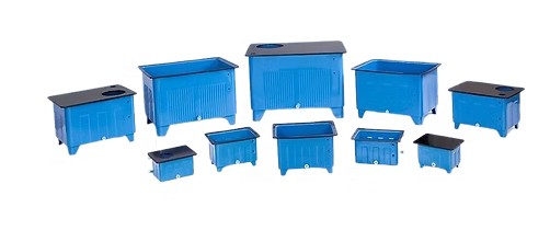
Description
Functions of a Hydraulic MS Tank
A hydraulic reservoir performs several important functions:
- Stores hydraulic oil
- Supplies hydraulic fluid to the pump
- Receives returning hydraulic fluid
- Provides space for thermal expansion of the fluid
- Allows air and entrained gas to separate from the hydraulic oil
- Provides an area where larger contaminants can settle
- Supports hydraulic-fluid cooling where applicable
- Provides mounting locations for selected hydraulic components
- Acts as the central fluid-storage point of the hydraulic circuit
The tank size and internal configuration should be selected according to the hydraulic system and operating conditions.
How a Hydraulic MS Tank Works
Hydraulic oil is stored inside the reservoir. The hydraulic pump draws fluid from the tank through the suction connection and sends it into the hydraulic circuit.
After passing through valves and actuators, the hydraulic fluid returns to the reservoir through the return circuit.
A simplified arrangement is:
MS Tank → Suction Line → Hydraulic Pump → Control Valves → Hydraulic Actuator → Return Line → MS Tank
The reservoir therefore forms an important part of the hydraulic fluid circulation system.
Main Components and Features
A hydraulic MS tank may include:
- Mild-steel tank body
- Suction connection
- Return connection
- Drain connection
- Oil level indicator
- Breather connection
- Filling arrangement
- Inspection or access cover
- Baffle plates
- Mounting brackets
- Filter mounting provisions
- Temperature-sensor mounting provision
- Hydraulic pump mounting provision
- Cleaning or maintenance access
- Lifting or handling provisions where required
The exact configuration depends on the hydraulic power pack and equipment design.
Mild Steel Construction
Mild steel is commonly used for hydraulic reservoir construction because it provides a practical combination of mechanical strength, fabrication flexibility, and suitability for industrial equipment.
The tank construction may include:
- Welded MS plates
- Reinforcement sections
- Mounting brackets
- Internal baffles
- Flanged or threaded connections
- Access covers
- Drain arrangements
Material thickness and fabrication details should be determined according to the tank size, mounting arrangement, operating environment, and application requirements.
Internal Baffles
Baffles can be incorporated into hydraulic reservoirs to influence the movement of hydraulic oil within the tank.
Depending on the design, baffles can help:
- Reduce direct turbulence between return and suction areas
- Encourage air separation
- Provide greater circulation path
- Reduce disturbance around the pump suction area
- Support settling of larger contaminants
The baffle arrangement should be designed according to the hydraulic system and tank configuration.
Hydraulic Tank Accessories
A hydraulic MS tank can be supplied with various accessories depending on the application.
These may include:
- Oil level gauge
- Level switch
- Breather filter
- Filling cap
- Return-line filter
- Suction strainer
- Drain plug
- Drain valve
- Temperature sensor
- Temperature gauge
- Inspection cover
- Magnetic separator
- Mounting brackets
- Hydraulic fittings
- Pump mounting arrangement
The required accessories depend on the hydraulic power-pack design.
Hydraulic MS Tank Applications
Hydraulic MS tanks are used in:
- Hydraulic power packs
- Industrial hydraulic systems
- Hydraulic presses
- Manufacturing machinery
- Machine tools
- Injection moulding machines
- Material-handling equipment
- Construction machinery
- Agricultural machinery
- Mining equipment
- Lifting equipment
- Packaging machinery
- Steel and metal-processing equipment
- Process machinery
- Hydraulic automation systems
- Custom hydraulic equipment
Hydraulic Reservoir Capacity
Tank capacity should be determined according to the hydraulic system requirements.
Important considerations include:
- Pump flow rate
- Hydraulic circuit volume
- Operating duty cycle
- Heat generation
- Available installation space
- Fluid expansion
- Return-flow conditions
- Required fluid residence time
- Equipment operating temperature
The reservoir should provide sufficient capacity for the hydraulic system while maintaining an appropriate operating oil level.
Hydraulic Tank Cooling
The hydraulic reservoir can contribute to heat dissipation, although the actual cooling capacity depends on tank size, surface area, ambient conditions, fluid circulation, and system heat generation.
For systems producing significant heat, additional cooling equipment such as a hydraulic oil cooler or heat exchanger may be required.
Hydraulic Tank Filtration
Hydraulic tanks can be integrated with filtration components such as:
- Suction strainers
- Return-line filters
- Breather filters
- Offline filtration connections
Proper filtration helps control contamination within the hydraulic fluid.
The filtration system should be selected according to the hydraulic components and required fluid cleanliness level.
Common Hydraulic MS Tank Problems
Potential hydraulic tank problems include:
- Oil leakage
- Weld failure
- Corrosion
- Damaged mounting points
- Contaminated hydraulic oil
- Blocked breather
- Damaged access cover seal
- Incorrect oil level
- Internal contamination
- Damaged suction connection
- Return-line turbulence
- Incorrect tank sizing
- Structural deformation
Regular inspection can help identify these issues before they affect the hydraulic system.
Inspection and Maintenance
Routine hydraulic tank inspection may include:
- Checking hydraulic oil level
- Inspecting oil condition
- Checking for external leakage
- Inspecting welds
- Checking for corrosion
- Inspecting mounting brackets
- Checking breather condition
- Inspecting suction and return connections
- Checking drain plugs and valves
- Inspecting access covers
- Cleaning internal contamination when required
- Checking tank temperature where applicable
The hydraulic oil should be maintained according to the hydraulic equipment manufacturer’s requirements.
Hydraulic Tank Cleaning
Contamination inside the reservoir can enter the hydraulic circuit and affect sensitive hydraulic components.
When cleaning a hydraulic MS tank:
- Isolate the hydraulic system.
- Drain the hydraulic fluid safely.
- Remove accumulated contamination.
- Inspect internal surfaces.
- Clean the reservoir using an appropriate method.
- Inspect suction and return connections.
- Check baffles and internal components.
- Replace damaged seals where required.
- Refill using suitable, clean hydraulic fluid.
- Follow the equipment manufacturer’s commissioning procedure.
The cleaning method should be compatible with the tank material, coating, seals, and hydraulic fluid.
Installation Considerations
When installing a hydraulic MS tank:
- Confirm the required reservoir capacity.
- Ensure the tank is properly supported.
- Verify suction and return connections.
- Provide sufficient access for maintenance.
- Install the breather correctly.
- Maintain suitable oil level.
- Avoid excessive vibration.
- Ensure the suction line is appropriately sized.
- Prevent contamination from entering the reservoir.
- Provide suitable drainage where required.
- Check all connections for leakage.
- Verify the tank is suitable for the installation environment.
Hydraulic MS Tank Selection
The correct hydraulic tank should be selected according to the hydraulic system and installation requirements.
| Specification | Requirement |
|---|---|
| Application | Hydraulic Power Pack / Industrial Hydraulic System |
| Tank Material | Mild Steel |
| Tank Capacity | According to Hydraulic System |
| Operating Oil Volume | Application Specific |
| Construction | Welded / Fabricated |
| Plate Thickness | According to Tank Design |
| Suction Connection | According to Pump |
| Return Connection | According to Hydraulic Circuit |
| Drain Connection | As Required |
| Breather | Required / As Specified |
| Oil Level Indicator | Required / Optional |
| Level Switch | As Required |
| Temperature Sensor | As Required |
| Return Filter | As Required |
| Suction Strainer | As Required |
| Internal Baffles | According to Design |
| Inspection Cover | As Required |
| Mounting | Equipment Specific |
| Surface Protection | According to Environment |
| Dimensions | According to Installation Space |
| Manufacturer / Part Number | As Required |
Replacement Considerations
When replacing a hydraulic MS tank, the replacement should not be selected only by its external dimensions.
Verify:
- Tank capacity
- Overall dimensions
- Suction connection location
- Return connection location
- Drain connection
- Breather arrangement
- Pump mounting
- Filter mounting
- Internal baffle configuration
- Oil level indicator
- Mounting points
- Hydraulic hose connections
- Installation orientation
- Available maintenance access
A tank with the same nominal capacity may still require different connections or mounting arrangements for compatibility with the existing hydraulic system.
Hydraulic MS Tank Supplier – Aegis Projects
Aegis Projects Technology Pvt. Ltd. supplies hydraulic MS tanks and hydraulic system components for industrial and commercial applications.
Our hydraulic range includes hydraulic MS tanks, hydraulic power packs, hydraulic pumps, hydraulic valves, hydraulic cylinders, hydraulic filters, filtration trolleys, hydraulic hoses, hydraulic fittings, hydraulic accumulators, and other hydraulic spare parts.
Hydraulic MS tanks can be selected according to the required reservoir capacity, mild-steel construction, pump and filter arrangement, suction and return connections, dimensions, mounting configuration, filtration requirements, and application conditions.
Contact Aegis Projects for hydraulic MS tanks and application-specific hydraulic reservoir solutions for your machinery and hydraulic power systems.