
Description
DWF-4.1/(18-25)-45 Natural Gas Compressor
High-Efficiency Natural Gas Compressor for Pipeline, CNG & Oilfield Applications
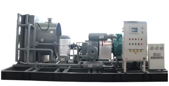
The DWF-4.1/(18-25)-45 Natural Gas Compressor is a high-pressure reciprocating compressor designed for natural gas boosting, transportation, storage, CNG compression, and oil & gas applications.
The compressor is engineered to handle natural gas with varying operating conditions and is suitable for applications where reliable pressure boosting and continuous gas compression are required.
With a processing capacity of approximately 500 Nm³/h, an inlet pressure range of 1.8–2.5 MPa.G, and a maximum exhaust pressure of 4.5 MPa.G, the DWF-4.1/(18-25)-45 provides controlled and stable natural gas compression.
The unit is powered by a 110 kW main motor and features a D-type symmetrical balanced structure, water-cooled system, oil-free lubrication configuration, and two-row, three-stage reciprocating piston compression.
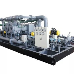
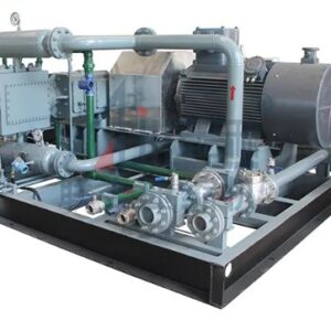
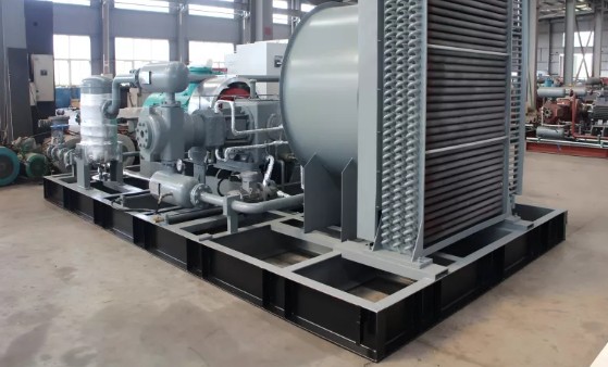
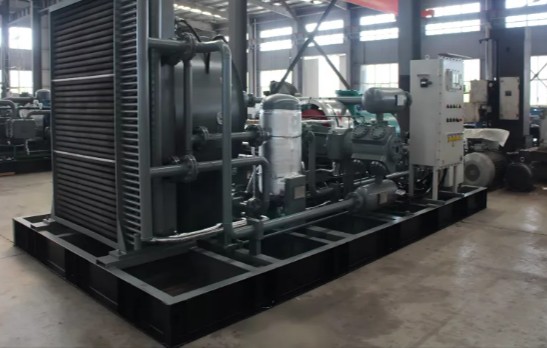
Its skid-mounted construction integrates the compressor and associated equipment into a compact package, simplifying transportation, installation, and commissioning.
Technical Specifications
| Parameter | Specification |
|---|---|
| Model | DWF-4.1/(18-25)-45 |
| Application | Natural Gas Compression |
| Processing Capacity | 500 Nm³/h |
| Inlet Pressure | 1.8–2.5 MPa.G |
| Inlet Temperature | ≤40°C |
| Exhaust Pressure | 4.5 MPa.G |
| Main Motor Power | 110 kW |
| Compressor Structure | D-Type Symmetrical Balanced |
| Compression Configuration | 2-Row, 3-Stage |
| Cooling System | Water-Cooled |
| Lubrication | Oil-Free Compression Configuration |
| Installation | Skid-Mounted |
| Approx. Dimensions | 5500 × 2200 × 2000 mm |
| Approx. Weight | 7 Tonnes |
Recommended Gas Conditions
The supplied technical specification identifies the following gas conditions:
| Gas Parameter | Specification |
|---|---|
| Methane (CH₄) | >95% |
| H₂S | ≤20 mg/m³ |
| Total Sulfur | ≤270 mg/m³ |
| CO₂ | ≤3% |
| Free Water | None |
| Dust Content | ≤5 mg/m³ |
| Dust Particle Size | ≤10 µm |
Final gas composition and operating conditions should be confirmed during project engineering and compressor selection.
Key Features
1. High-Efficiency Three-Stage Compression
The DWF-4.1/(18-25)-45 utilizes a two-row, three-stage reciprocating piston compression system.
The multi-stage configuration progressively increases gas pressure, allowing the compressor to handle the required pressure ratio while supporting controlled compression temperatures and stable gas output.
Key benefits include:
- Progressive pressure increase
- Stable discharge pressure
- Efficient high-pressure compression
- Controlled compression temperatures
- Suitability for continuous operation
- Reliable natural gas delivery
The compressor can be used in applications requiring consistent gas pressure for pipeline transportation, CNG systems, storage, and industrial processes.
2. Water-Cooled Compression System
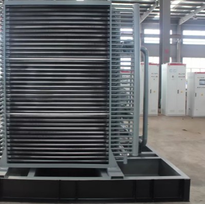
Compression generates heat that must be effectively managed during continuous operation.
The DWF-4.1/(18-25)-45 incorporates a water-cooled system designed to dissipate heat generated during the compression process.
Effective cooling helps maintain suitable operating temperatures and supports reliable compressor operation during extended-duty cycles.
For projects where water availability is limited, alternative cooling configurations may be considered depending on the operating environment and project requirements.
3. D-Type Symmetrical Balanced Structure
The compressor incorporates a D-type symmetrical balanced reciprocating structure designed to support stable mechanical operation.
The balanced configuration helps distribute reciprocating forces and can contribute to:
- Reduced vibration
- Stable operation
- Lower mechanical stress
- Improved equipment durability
- Reliable continuous operation
This makes the compressor suitable for industrial installations where operational stability is important.
4. Oil-Free Compression Configuration
The compressor incorporates a configuration designed to minimize the possibility of lubricating oil entering the gas compression chamber.
A double-middle-body structure separates the lubrication section from the compression section, helping maintain cleaner compressed natural gas.
This is particularly useful where downstream equipment such as:
- Gas pipelines
- Storage systems
- CNG equipment
- Processing systems
requires controlled gas quality.
5. Robust Mechanical Construction
The compressor uses robust materials and structural components designed for high-pressure natural gas compression.
Crankcase
The crankcase is manufactured from gray cast iron and incorporates provisions for:
- Lubricating oil management
- Oil level observation
- Oil filling
- Temperature measurement
- Maintenance access
Cylinder & Cylinder Head
The cylinder and cylinder head can utilize gray cast iron or forged steel, depending on the final configuration.
These components are designed to withstand the mechanical loads and pressure conditions associated with high-pressure reciprocating compression.
6. Skid-Mounted Integrated Design
The compressor, motor, and associated auxiliary equipment can be assembled on a common skid base.
This integrated configuration provides:
- Easier transportation
- Simplified installation
- Reduced site assembly
- Pre-aligned equipment
- Compact equipment arrangement
- Faster commissioning
- Simplified project integration
The skid-mounted package is suitable for both permanent installations and selected mobile or field applications.
7. Maintenance-Friendly Configuration
The compressor is designed with practical access to key maintenance points.
Depending on the final configuration, accessible components may include:
- Oil drainage points
- Filters
- Lubrication components
- Inspection points
- Instrumentation
- Compressor valves
- Control components
A manual ball valve can be provided for crankcase oil drainage to simplify routine maintenance.
Customizable Compressor Configuration
The DWF-4.1/(18-25)-45 can be configured according to project-specific operating conditions and installation requirements.
Structural Configuration
Different compressor structural arrangements may be considered depending on project requirements, including:
- D-Type
- M-Type
- S-Type
- W-Type
- V-Type
- Z-Type
The final structure can be selected according to equipment layout, available space, process requirements, and compressor duty.
Cooling Options
Depending on the installation environment, cooling options can include:
- Water cooling
- Air cooling
- Mixed cooling
Water cooling can be selected where a suitable water supply is available, while air cooling may be considered for dry or water-constrained environments.
Installation Options
The compressor can be configured for:
- Fixed installation
- Skid-mounted installation
- Mobile applications
- Cabin-type packages
This flexibility allows the compressor to be adapted for permanent CNG stations, industrial plants, remote gas facilities, and field applications.
Drive Options
The standard configuration uses an electric motor drive.
For remote locations with limited grid access, alternative drive configurations such as diesel-engine drive may be considered, subject to project requirements.
Applications
Natural Gas Pipeline Boosting
The DWF-4.1/(18-25)-45 can be used for natural gas pipeline pressure boosting to support gas transportation through pipeline networks.
It can help maintain the pressure required for downstream transmission and distribution systems.
Natural Gas Storage
The compressor can support selected underground or high-pressure natural gas storage applications, where gas needs to be compressed before storage or transferred between process stages.
CNG Stations
The DWF-4.1/(18-25)-45 can be integrated into CNG compression systems where natural gas needs to be compressed for storage and vehicle refueling.
The compressor’s configuration can be adapted according to the required CNG station flow and pressure conditions.
Oil & Gas Field Operations
The compressor can be used in oil and gas field applications for:
- Associated gas recovery
- Gas boosting
- Field gas transportation
- Gas recovery from production operations
- Selected drainage gas applications
Recovering and utilizing associated gas can help reduce gas wastage and improve overall resource utilization.
Industrial Gas Applications
The compressor can support industrial systems requiring reliable compressed natural gas.
Potential applications include:
Pharmaceutical & Brewing
Compressed gas can be used for selected agitation and process applications.
Chemical Industry
The compressor can support pressurized gas transportation and transfer in suitable chemical processes.
Food & Beverage
Compressed gas can be utilized for selected bottle blow-moulding applications.
Machinery Manufacturing
Compressed gas can support parts cleaning and dust removal processes.
Patented Design Features
The supplied technical documentation identifies several patented design features associated with the compressor:
Piston Rod Thread Protective Sleeve
Patent No.: ZL 2017 2 1907021.7
Piston Ring Support Device
Patent No.: ZL 2018 2 0294776.2
Range Piston for Symmetrical Balanced Compressors
Patent No.: ZL 2017 2 190177.0
Integrated Long-Short Double Compartment
Patent No.: ZL 2018 2 0294762.0
These patent references are based on the supplied technical information and should be verified against current manufacturer documentation before being used as independent product claims.
Key Advantages
High-Pressure Natural Gas Compression
Designed for reliable natural gas pressure boosting up to 4.5 MPa.G discharge pressure.
Three-Stage Compression
Two-row, three-stage compression provides progressive pressure increase and stable gas delivery.
Water-Cooled Design
Effective thermal management for continuous natural gas compression applications.
Oil-Free Compression Configuration
The double-middle-body arrangement helps minimize lubricant contamination of the compressed gas.
Skid-Mounted Package
Simplifies transportation, installation, commissioning, and project integration.
Flexible Installation
Suitable for CNG stations, pipeline systems, industrial plants, and selected oilfield applications.
Customizable Configuration
Structural arrangement, cooling system, installation format, and drive system can be configured according to project requirements.
Aegis Projects – Natural Gas Compression Solutions
Aegis Projects Technology Pvt. Ltd. provides engineered solutions for natural gas compressors, CNG compressor skids, pipeline gas boosting systems, oil & gas compression, industrial gas systems, automation, instrumentation, and turnkey project requirements.
Our engineering and project support can include:
- Compressor package selection
- Skid integration
- Gas piping
- Valves and fittings
- Instrumentation
- Electrical systems
- PLC controls
- Safety and shutdown systems
- Cooling systems
- DCS integration
- Installation and commissioning support
For the DWF-4.1/(18-25)-45 Natural Gas Compressor or a customized natural gas compression package, share your required flow rate, inlet pressure, discharge pressure, gas composition, operating temperature, cooling requirements, and installation conditions with Aegis Projects.
Aegis Projects Technology Pvt. Ltd. — Engineered Natural Gas Compression, CNG & Industrial Automation Solutions.
Technical Parameter